Thegrease and oil separator, according to EN 1825 a grease trap, sometimes referred to as a grease trap, is used for wastewater treatment especially in areas where grease and oil are likely to occur. Grease in the sewage system has adverse consequences such as clogged drains and unpleasant odours.
Oil and grease separators are installed in the vicinity of kitchens, especially school and factory kitchens, restaurants, hotels, canteens, cake shops and other establishments processing fats and oils.
Description and function of the grease trap
The grease trap is designed as an all-plastic, self-supporting tank with variable height - the height of the extension is controlled according to specific requirements. Similar to the oil separator, the grease trap has a wall dividing the space into individual functional parts.
First, water containing grease and suspended solids flows into the sludge compartment where coarse dirt settles. The sewage water then flows over the transverse wall into the settling area where gravity separation of the grease at the surface takes place. The grease layer is either mechanically removed directly from the surface or can be raked over the wedge of the partition into the storage area.
The purified water then flows under the bore wall into an outlet connected to the sewer. The interceptor is vented through a pipe above the surface to which a vent pipe must be connected.
Types of oil and grease separators Morava Ekol
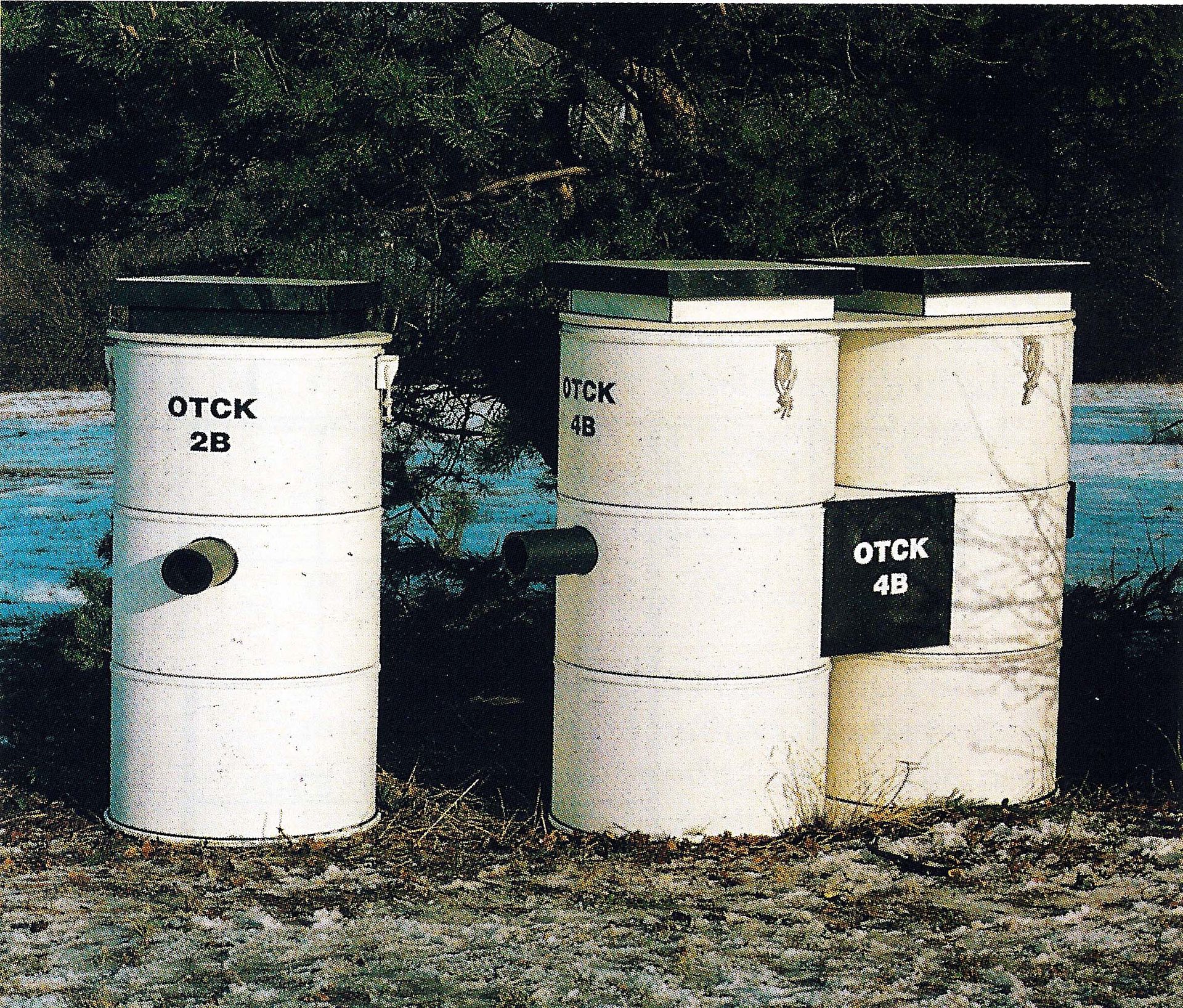
We use integral and linear polypropylene (PP) to manufacture the separators. You can choose from 2 types of oil and grease separators, namely:
- OTC
- OTCK - has no storage space.
Both types can be passable or non-passable. In the traversable design, the separator serves as a lost formwork for concreting and the inlets are adapted for fitting heavy steel-lined road covers.
Technical data of grease traps
| Type | OTC 02 | OTC 04 | OTCK 02 | OTCK 04 |
| Height [mm] | 1 500 x 1 160 | 1 000 | 700 | 1 500 |
| Height [mm] | according to customer requirements | |||
| Max. weight [kg] | 350 | 400 | 80 | 170 |
| Flow rate [1/sec] | 2,0 | 4,0 | 2,0 | 4,0 |
| Max. number of meals | 400 | 1 200 | 400 | 1 200 |
| Tank type | Self-supporting made of polypropylene | |||
The inlet opening is 160 mm, the outlet and vent is a PP pipe with a diameter of 110 mm. All these diameters can be changed according to customer needs.
Standard: EN 1825 Grease traps
- Part 1 Design and testing (for the manufacture of grease traps)
- Part 2 Selection of nominal size, installation, operation and maintenance (for the design and operation of traps)
EN 1825-2 provides requirements and guidelines for the selection of the size of grease traps, their use, fitting, connection to piping, installation, operation, inspection and maintenance of grease traps.


